Dielectric Elastomer Actuators with Biphasic Ag–EGaIn Electrodes
Mahmoud Tavakoli
Manuel Reis Carneiro
Carmel Majidi
A new electrode architecture for dielectric elastomer actuators (DEAs) is introduced in which a soft polyacrylate film is coated with a biphasic mixture of silver, indium, and gallium. This Ag–In–Ga coating functions as a soft electrode that is ultrathin, highly compliant, highly conductive, stretchable, and non-smearing. Compared to carbon grease, sputter-deposited metal coating, and particle-filled conductive elastomers, this biphasic coating exhibits a unique combination of solid-state integrity, extreme mechanical compliance, and low electrical resistivity. Herein, how DEAs with an Ag–In–Ga coating exhibit a 5 larger actuation speed compared to carbon-coated dielectric films is shown. The influence of coating thickness on the mechanical stiffness and blocking force is also
examined.
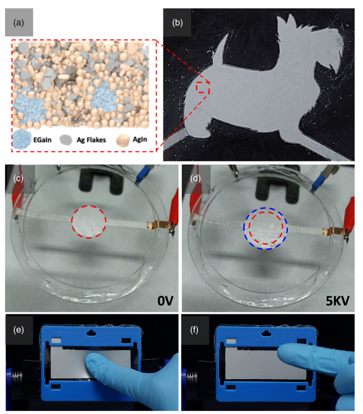
Ag–In–Ga ink-based dielectric elastomer actuators. A) Microstructure of the Ag–In–Ga conductive ink—Reproduced with permission.[13] Copyright 2021 American Chemical Society. B: DEA with intricate and detailed shape that can be fabricated with the proposed method. C,D) Ag– In–Ga ink-based radial DEA in the unactuated and actuated states, where radial expansion of the ink electrodes can be observed. E) Ag–In–Ga DEA being rubbed with a finger. F) No smearing, smudging, or displacement of the electrode is observed afterward, nor is the glove marked.


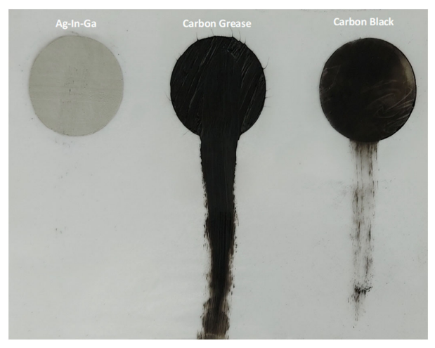
The non-smearing nature of the Ag–In–Ga ink, which is not displaced when a finger slides over it, contrary to what happens with CG and CB.

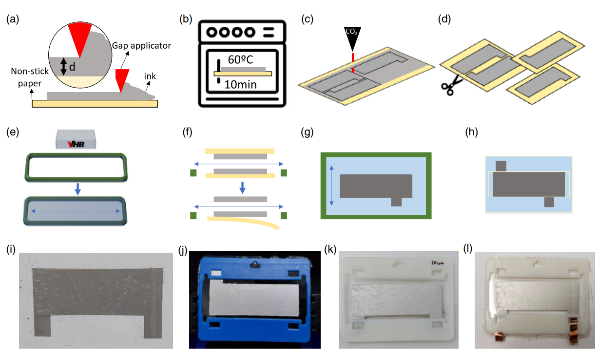
DEA fabrication. A) An ink film of desired thickness (d) is applied with a gap applicator on top of nonstick paper and B)let to cure for 10 min at 60 C. C) The electrode shape is patterned on the ink film with a CO2 laser and D) the excess ink is peeled off from around the electrodes and the electrodes are separated from each other. E) VHB tape is uniaxially stretched over a rigid frame with a prestretch ratio of 3.5. F) Two electrodes are bonded on each side of the dielectric and the backing paper is peeled off, leaving a G) full DEA behind. H) A new 3D-printed rigid frame is adhered on both sides of the DEA and it is separated from the previous larger stretching frame. I,J,K,L) Uniaxially prestretched DEAs with Ag–In–Ga ink Electrodes.

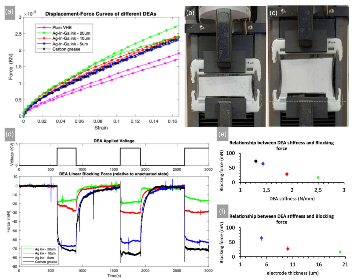
A) Tensile displacement–force curves for pristine VHB and VHB with attached CG and Ag–In–Ga electrodes, for stiffness estimation. B) Unstretched DEA. C) Stretched DEA during tensile testing. D) Blocking force of various DEAs with electrodes of different thicknesses, actuated at 4 kV. E) Relation between DEA stiffness and its actuation performance in terms of blocking force. F) Relation between electrode thickness and DEA blocking force.

