Untethered Disposable Health Monitoring Electronic Patches with an Integrated Ag2O–Zn Battery, a AgInGa Current Collector, and Hydrogel Electrodes
Cristina Leal
Pedro Alhais Lopes
Arménio Serra
Jorge F. J. Coelho
Aníbal T. de Almeida
Mahmoud Tavakoli
Stretchable electronics stickers that adhere to the human skin and collect biopotentials are becoming increasingly
popular for biomonitoring applications. Such stickers include electrodes, stretchable interconnects, silicon chips for processing and communication, and batteries. Here, we demonstrate a material architecture and fabrication technique for a multilayer, stretchable, low-cost, rapidly deployable, and a disposable sticker that
integrates skin-interfacing hydrogel electrodes, stretchable interconnects, and a Ag2O−Zn (silver oxide−zinc) battery. In addition, the application of a printed biphasic current collector (AgInGa) for the Ag2O−Zn battery is reported for the first time. Surprisingly, and unlike previously reported batteries, the battery capacity increases after being subjected to strain cycles and reaches a record-breaking areal capacity of 6.88 mAh cm−2 post stretch. As a proof of concept, an application of heart rate monitoring is presented. The disposable patch is interfaced with a miniature battery-free electronics circuit for data acquisition, processing, and wireless transmission. A version of the patch partially covering the patient’s chest can supply enough energy for continuous operation for ∼6 days.

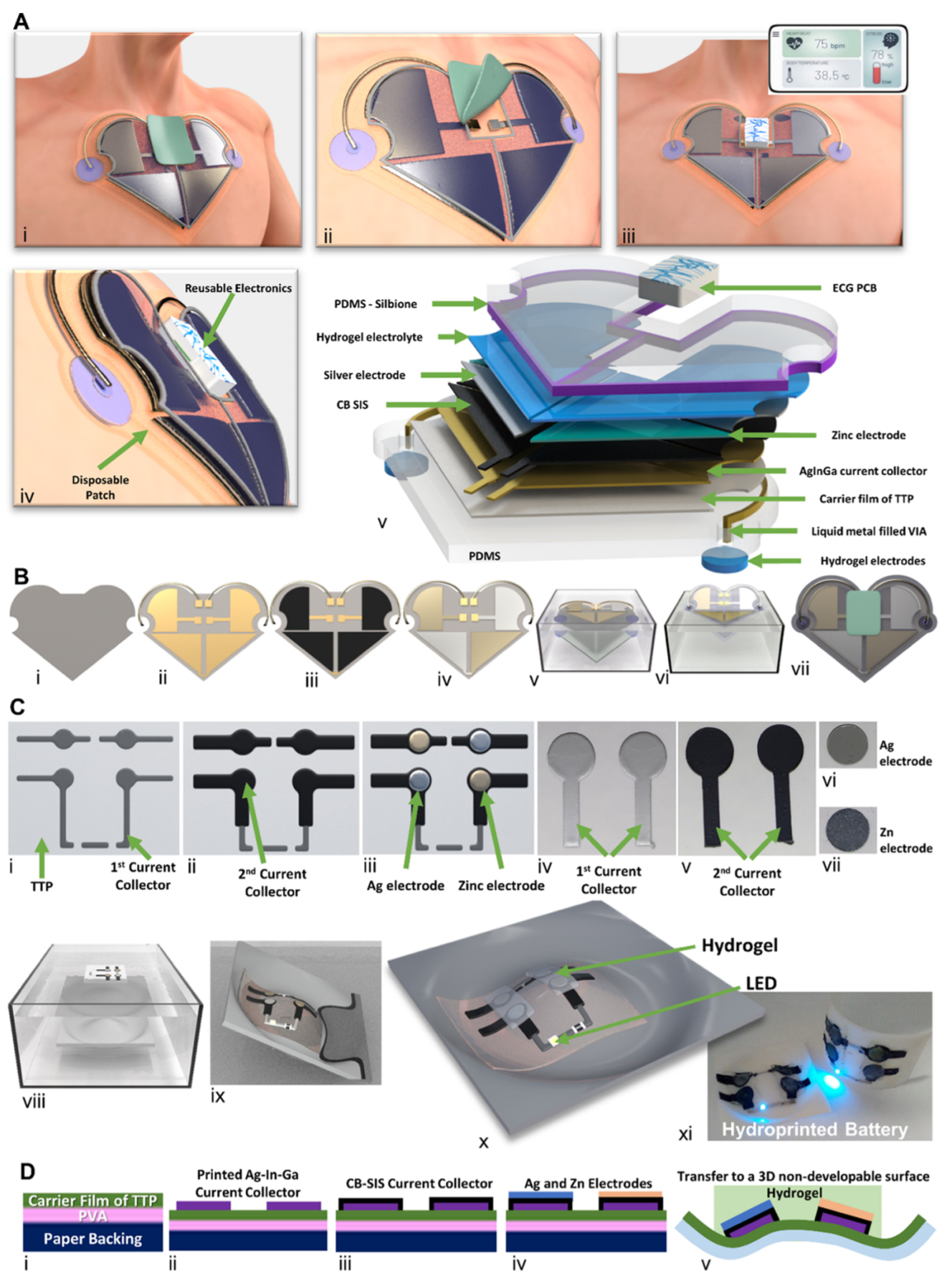
(A) Application of a disposable patch with an integrated Ag2O−Zn battery, hydrogel electrodes, and electrical interconnects: (i) schematic illustration of the disposable biomonitoring patch and the Ag2O−Zn battery on a model; (ii) removal of the protection film four connection leads exposed to interface with ECG−PCB; (iii) ECG−PCB box for data acquisition, processing, and communication, interfaced with the patch and electrophysiological data transmission to a smartphone; (iv) side view of patch; and (v) composition of all layers of the patch. (B) Steps for the fabrication of the battery: (i) transfer tattoo paper substrate; (ii) printed AgInGa layer for the current collector and electrical interconnects; (iii) CB−SIS layer is deposited by screen printing; (iv) Ag and Zn electrodes are placed over the current collectors; (v) hydrotransfer process dissolution of the water-soluble film in TTP, resulting in separation of the backing paper and floating of the thin-film carrier with the battery on water; (vi) battery transferred over the PDMS (with embedded hydrogel electrodes); and (vii) hydrogel electrolyte and PDMS lid application. (C) Hydroprinted battery, transferred over nondevelopable 3D surface: (i) printed AgInGa current collector; (ii) printed CB−SIS layer; (iii) application of Ag and Zn electrodes; (iv) photo of the 1st current collector; (v) photo of the 2nd current collector; (vi) photo of silver electrode; (vii) photo of zinc electrode; (viii) hydrotransfer process (3D printed piece inside the water tank and the battery floating on the surface); (ix) the battery is transferred to the surface of the nondevelopable 3D piece; (x) hydrogel electrolyte and LED connected; and (xi) photo of the battery
transferred over a piece, lighting up an LED. (D) Sideview of the layers of the Ag2O−Zn battery.
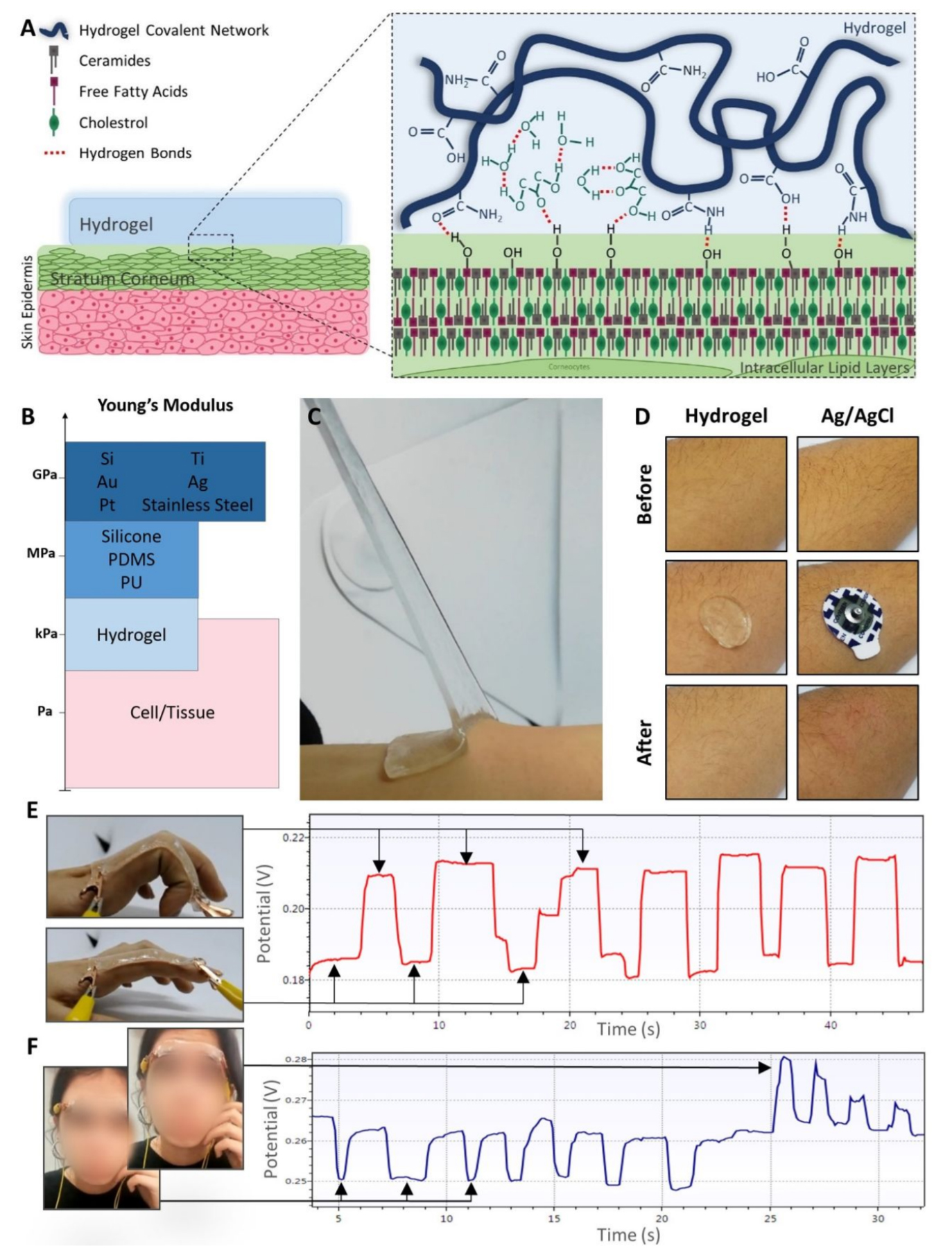
Hydrogel Functionality. A) Representation of the hydrogel network and double solvent and its interaction with the skin epidermis. B) Young’s Modulus of the biological tissues and cells against the commonly used materials in bioelectronics, and Hydrogels. Figure adapted from 60. C) Peeling off the highly stretchable and adhesive Hydrogel from the skin. D) Skin reaction to the hydrogel electrode compared to the Ag/AgCl electrode. E) Hydrogel potential
variance with finger movement. F) Hydrogel potential variance with facial expressions when applied on the forehead.


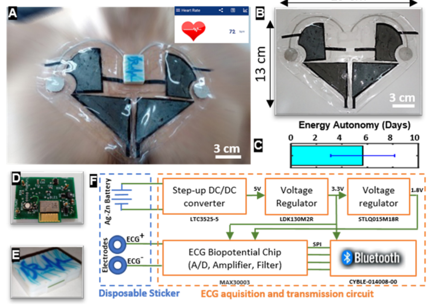
(A) Biomonitoring patch being worn by a volunteer. (B) Biomonitoring patch with the transferred battery prior to the transfer. (C) Bar graph depicting the energy autonomy of the battery. (D, E) ECG printed circuit board that acquires and sends the bpm values. (E) Box for the ECG−PCB with connection leads to interface the disposable sticker. (F) Schematics diagram showing the working principle and main components of the ECG−PCB.

