

State estimation and path following on curved and flat vertical surfaces with Omniclimber robots:
People involved:
- Mahmoud Tavakoli
- Lucio Sgrigna
- Carlos Viegas
- Anibal T de Almeida
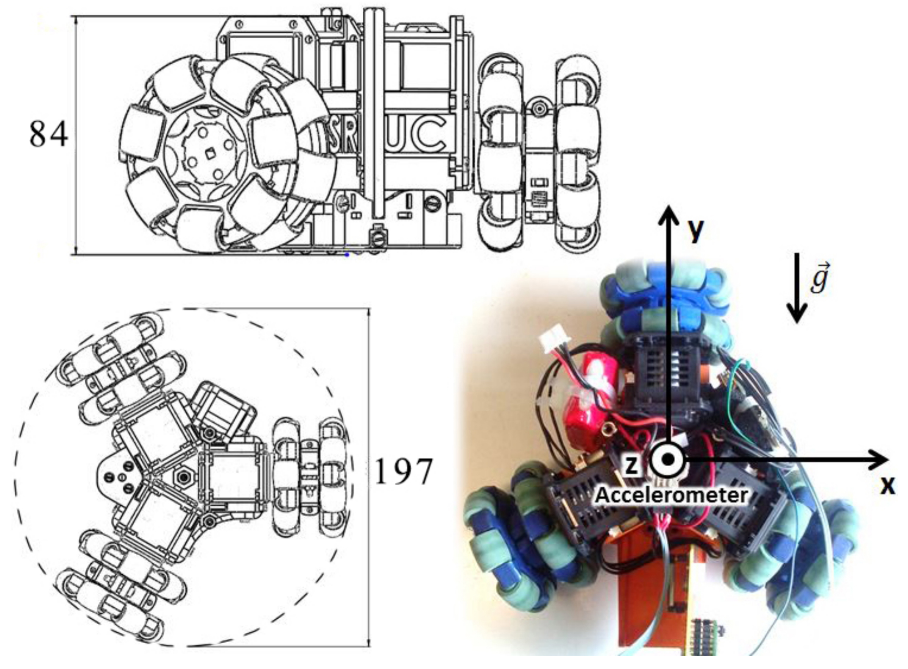
OmniClimber-VI, showing dimensions and reference axis.
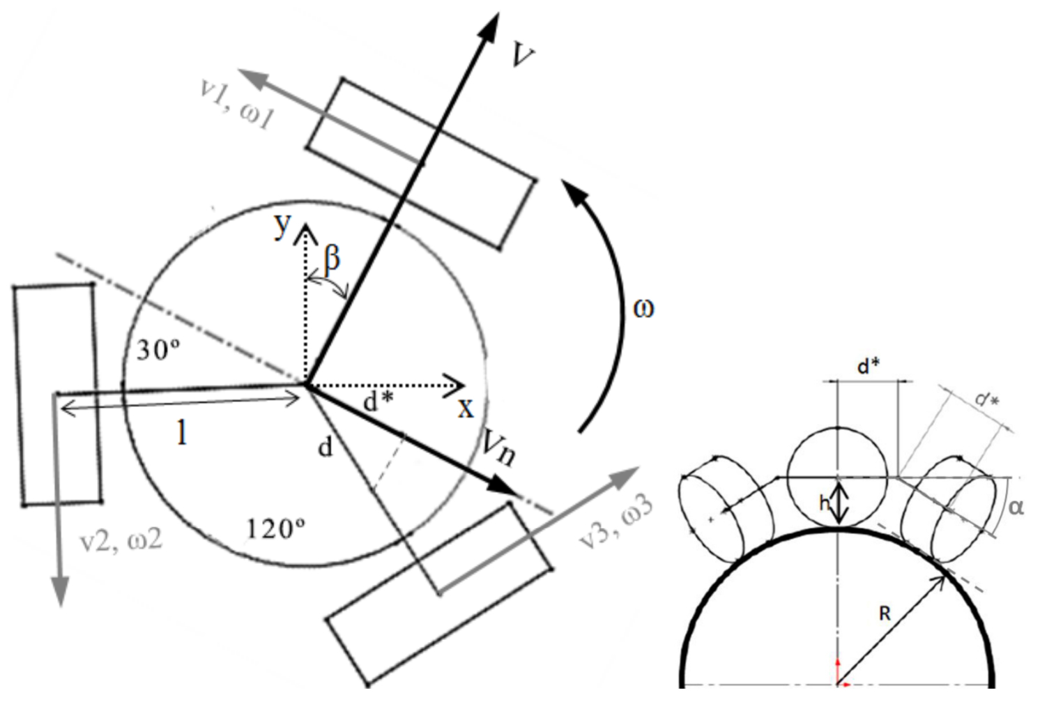
Kinematics model of the 3 wheeled omnidirectional platform with representation of relevant axis and velocities. Notation: x, y – static world axis; β – Yaw angle [rad]; l – distance between the wheels and center of the robot [m]; v1, v2, v3 – wheels linear velocity [m/s]; ω1, ω2, ω3 – wheels angular velocity [rad/s]; V, V n – robot front and lateral velocity [m/s]; ω – robot angular velocity [rad/s]; α – Bending angle of the arms [rad]; R – radius of the structure [m]; h – height of the CG of the robot (roughly equal to the radius of the omnidirectional wheel) [m]; d – half length of the robot arm [m];
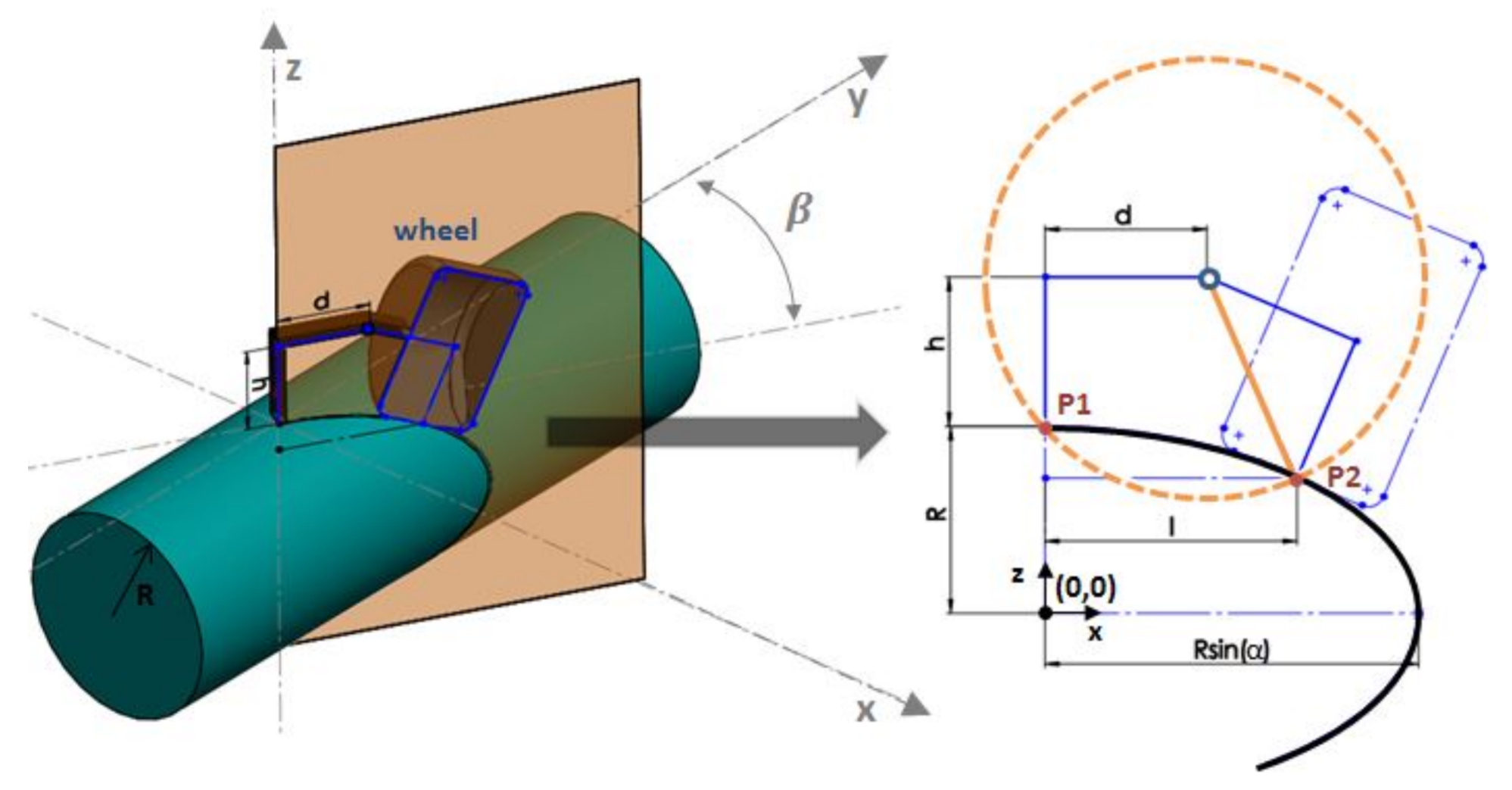
Geometric relations used to determine the distance l between the point of contact (POC) with the surface and the center of the robot. Notation: x, y, z – static world axis; β – Yaw angle [rad]; R – radius of the structure [m]; h – height of the CG of the robot (roughly equal to the radius of the omnidirectional wheel) [m]; d – half of the robot arm length [m]; l – distance between the wheel POC and center of the robot [m];
3D simulation for new kinematic model validation.
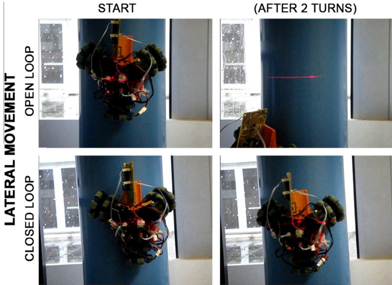
Snapshots from the Omniclimber experiments on a pole of 220mm diameter, without and with the new controller. Rotating around the pole while keeping the robots orientation constant.
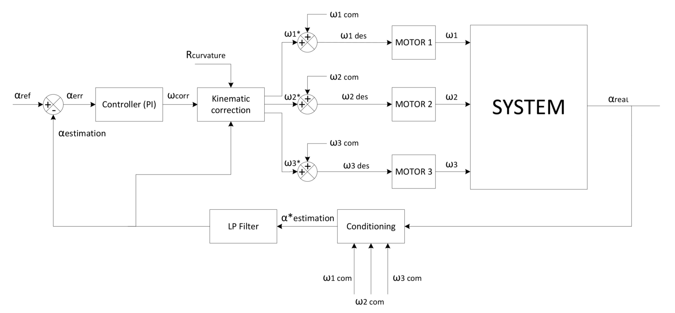
Closed loop control diagram.
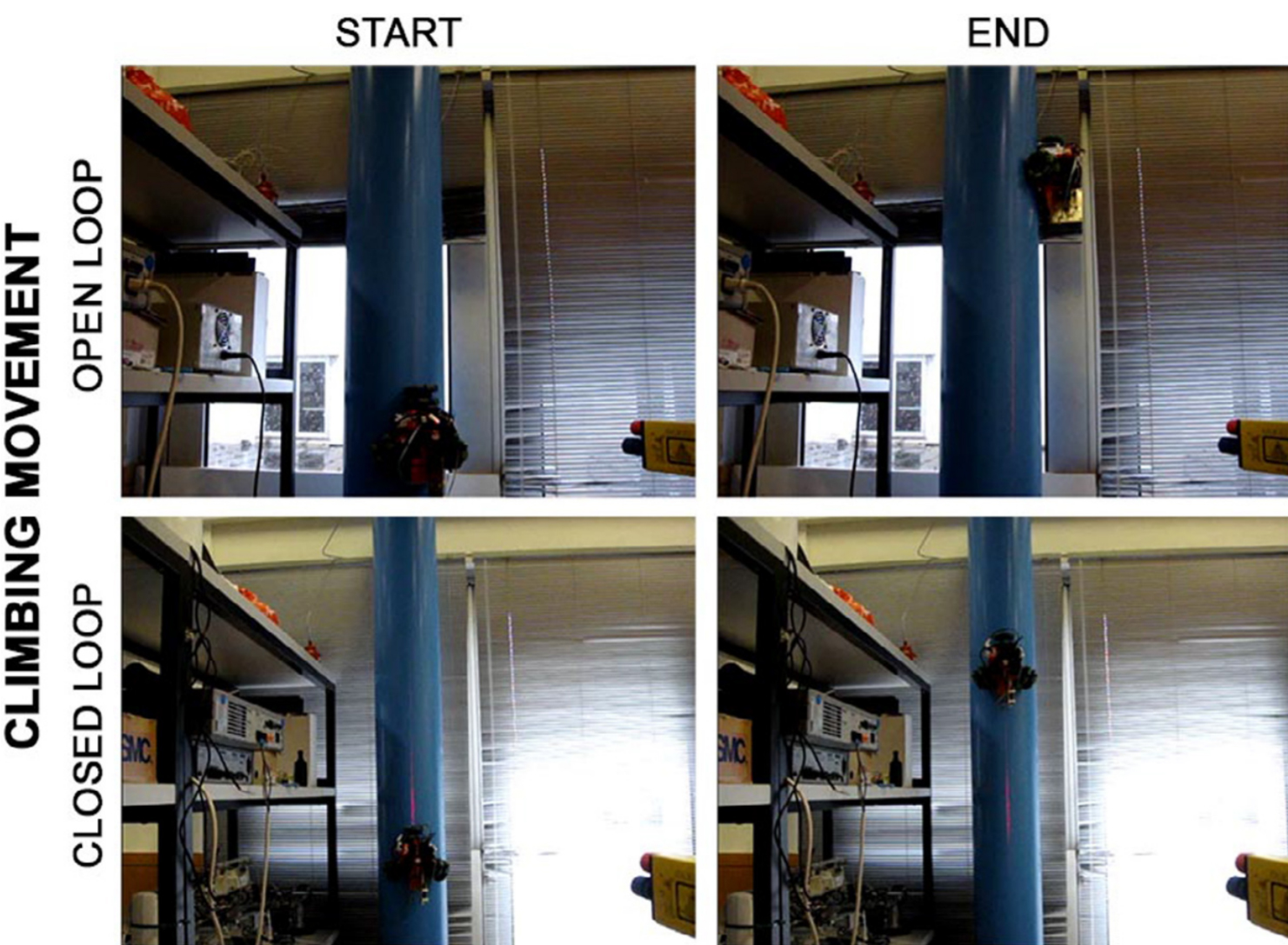
Snapshots from the Omniclimber experiments on a pole of 220mm diameter, without and with the new controller. Moving vertically parallel to the pole axis.
State estimation and path following on curved and flat vertical surfaces with Omniclimber robots: Kinematics and control.
M. Tavakoli, L. Sgrigna, C. Viegas and A. T. de Almeida, “State estimation and path following on curved and flat vertical surfaces with Omniclimber robots: Kinematics and control,” 2015 IEEE/RSJ International Conference on Intelligent Robots and Systems (IROS), Hamburg, 2015, pp. 3326-3331. doi: 10.1109/IROS.2015.7353840