

Multi-Electrode Printed Bioelectronic Patches for Long-Term Electrophysiological Monitoring
Mahmoud Tavakoli
Manuel Reis Carneiro
Carmel Majidi
Health monitoring systems have undergone significant developments in the last decade, mainly thanks to the advent of wearable technology, which contrasts with the bulky, rigid, and obstructive equipment commonly found in clinics and hospitals.[1]
In the last few years, wearable devices were proposed for long-term and continuous electrophysiological monitoring.
This includes both e-textiles or ultrathin adhesive e-skins for the recording of biopotentials (electrocardiography – ECG,[2–5] electromyography – EMG,[6–9] electroencephalography – EEG,[10–14] or electrooculography – EOG),[9,12,15]respiration rate,[16–18]temperature,[19,20]pulseoximetry,[21,22]or human motion.[23,24]The ultimate goal is to enable long-termelectrophysiological monitoring, increasethe patient comfort during such analysis,and to reduce the healthcare burden byenabling remote patient monitoring – anaspect to which more importance hasbeen given after the recent COVID-19pandemic.[25]It also allows patients to bemonitored 24/7 while remaining in theirhomes and keeping their routines, whichhas been proven to speed-up recoverieswhile reducing healthcare costs.[26,27]This has been a major driving force forthe novel field of stretchable and thin-filmelectronics, which intends to develop advanced electronic systems that can adapt to the dynamic morphology of the humanskin. Materials and fabrication techniques for advancement ofthis field have been a major focus of investigation in the pastfew years.[28,29]This includes techniques for implementationof deterministic structures,[30]conductive composites,[31–36]and liquid metals,[37–39]which include soft lithography,[40–44]laser patterning,[45–49]stencil printing,[12,34,44,50]or direct deposition.[16,31,32,46,49]Another requirement is the integration ofskin-interfacing electrodes to collect biopotentials from theepidermis for EMG/ECG/EEG monitoring, which includethe traditional Ag/AgCl electrodes, novel wet hydrogel electrodes[51,52]as well as printed dry electrodes based on carbon,[12]silver[2,12,20,53,54]or polymers such as PEDOT:PSS.[55]Incorporation of thin-film printed electrodes generally is preferable dueto higher user comfort, easier implementation, a more desirable form factor, and the possibility of very low-cost and scalablefabrication. However, compared to gel electrodes, these printeddry electrodes suffer from a lower skin-conformance, a higherelectrode-skin impedance, and thus a lower signal quality.[56]In summary, implementation of a truly wearable, comfortable, thin-film, and low-cost electrophysiological monitoringsystem that provides a medical-grade interfacing quality is stillnot demonstrated. A few implementations of “electronic tattoos”[5,15,21,31,57]are valuable progress, however, these usuallyfall short either in terms of the required robustness for longterm monitoring, or in terms of signal quality that usually getsdegraded over time due to reduced electrode-skin conformance.
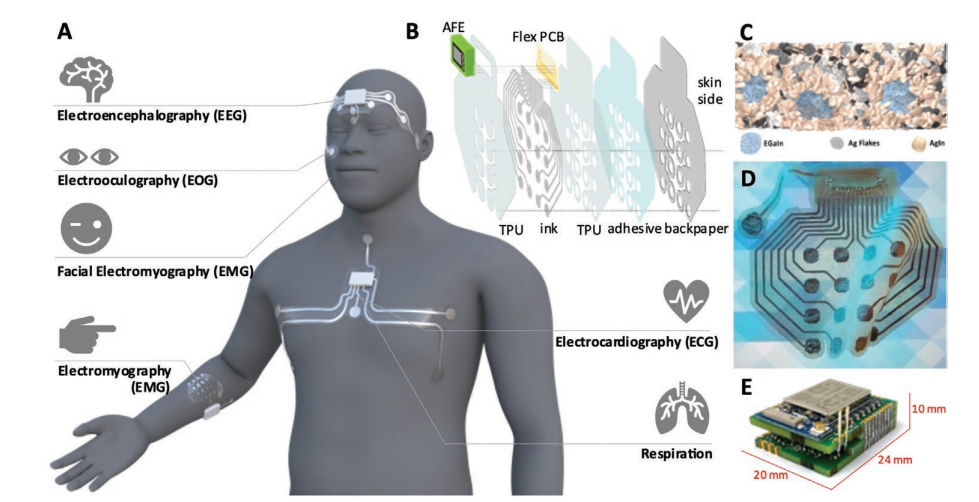
A) Depending on its shape and placement in the body, the proposed adhesive patches can be used for detection of multiple electrophysiological signals: brain waves (EEG), eye movement (EOG), neuromuscular activity (EMG), cardiac activity (ECG), and respiration. B) The various layers and components that compose the e-patch. C) Schematic model of the trinary microstructure of the biphasic conductive polymer. Adapted with permission from Ref. [29]. Copyright 2021 American Chemical Society. D) Fully printed flexible adhesive patch on a patterned background, evidencing the transparency of the substrate. E) Rigid analog front end.
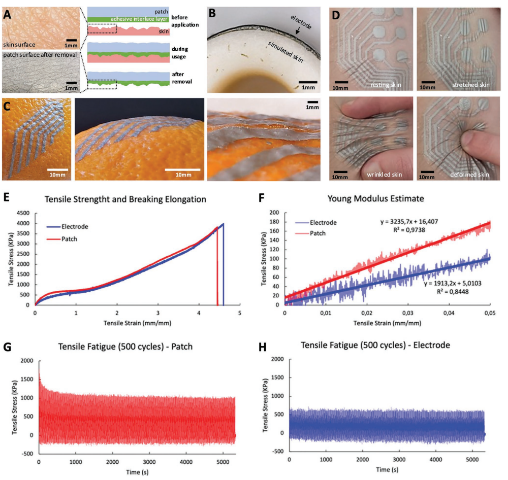
A) Skin wrinkles are imprinted on the adhesive interface layer of the patch. B) Cross-section image of a printed electrode conformed to a nonplanar skin replica. C) Images of a patch conformed to the rough surface of an orange peel. D) The dynamic conformal nature of the e-patch: it keeps its conformability to the skin even under deformation. E) Strain–Stress curves obtained from quasi-static tensile testing for electrode and patch stackups showing a rupture strain ≈450% for both cases. F) Young’s modulus for both multi-layer stackups obtained from linear regression. G) Fatigue testing of the 4-layer patch stack for 500 cycles at a strain of 30%. H) Fatigue testing of the 2-layer electrode stack for 500 cycles at a strain of 30%. In plots E–H, one sample per test was used.
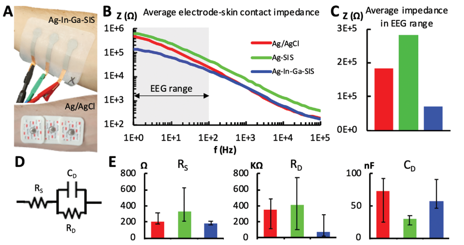
A) (top) Ag–In–Ga–SIS patch with each electrode having an active contact area of 132.73 mm2 with the skin and (bottom) Ag/AgCl electrodes with each electrode having an active contact area of 176.71 mm2 with the skin – placed on the user’s ventral forearm. B) Bode plots of the electrode-skin impedance for different electrode types, averaged across the measurements for subject one to nine. C) Average impedance in the EEG range (1–100 Hz), averaged for subjects one to nine. D) Electrode–skin interface equivalent circuit. E) Equivalent circuit’s parameters average for subjects one to nine and maximum/minimum error bars. (n = 1 for each of the nine subjects).
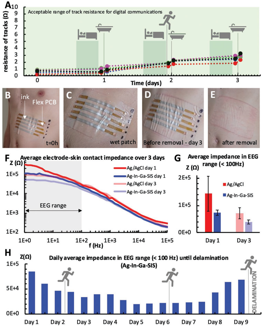
Aging of patch. A) Variation of ink resistance over 3 days for five samples, while performing everyday activities such as sleeping, jogging, and showering. B) Patch with printed Ag–In–Ga–SIS conductive lines with flexible contacts for easy measurement of resistance, adhered to the subject’s abdomen (t = 0 h). C) Wet patch after showering (t = 24 h). D) Patch right before removal (t = 73 h). E) skin redness after patch removal. F) Evolution of electrode-skin impedance over the course of 3 days for standard Ag/AgCl electrodes (176.7 mm2 contact area per electrode) and printed Ag-In-Ga-SIS electrodes (132.7 mm2 contact area per electrode) – averaged for three measurements with distinct electrode sets. G) Average electrode-skin impedance for Ag/AgCl electrodes and printed Ag–In–Ga–SIS electrodes in the EEG range over the course of 3 days – averaged for three measurements. H) Average impedance of Ag–In–Ga–SIS electrodes (132.7 mm2 contact area per electrode) measured twice a day until delamination of the patch on day 9. Single measurements were taken for one user and the test included daily showering, three 45 min runs and normal daily activities.
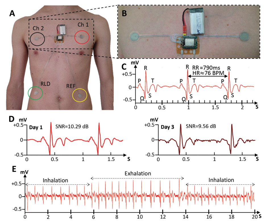
A) Electrode positioning for one-Lead Electrocardiography patch. B) Close-up image of the patch showing the two measuring electrodes, analog-front-end, and battery. C) Acquired ECG signal and identification of normal ECG features such as the QRS Complex and P and T waves. An RR interval of 790 ms, from which a heartrate measurement of 76 bpm can be derived. D) Comparison between ECG signal on 1st day and after 3 days of the patch being used. Although Signal to Noise Ratio decreases, normal ECG features are still visible. E) Respiration signal can be derived from the ECG measurement thanks to the change in amplitude of the QRS complex during respiration cycles.
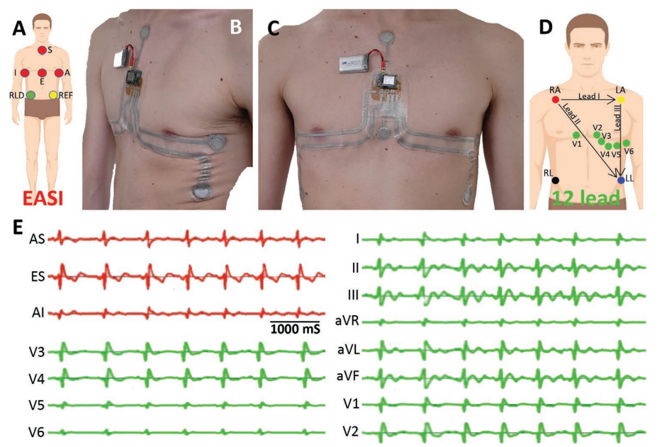
A) Position of ECG recording electrodes according to the EASI montage. B,C) Multielectrode ECG patch based on the EASI system. D) Position of the ECG recording electrodes in a conventional 12-lead system. E) Electrocardiogram signals directly acquired from the EASI patch (in red) and full 12-lead ECG derived from the EASI recordings (in green).
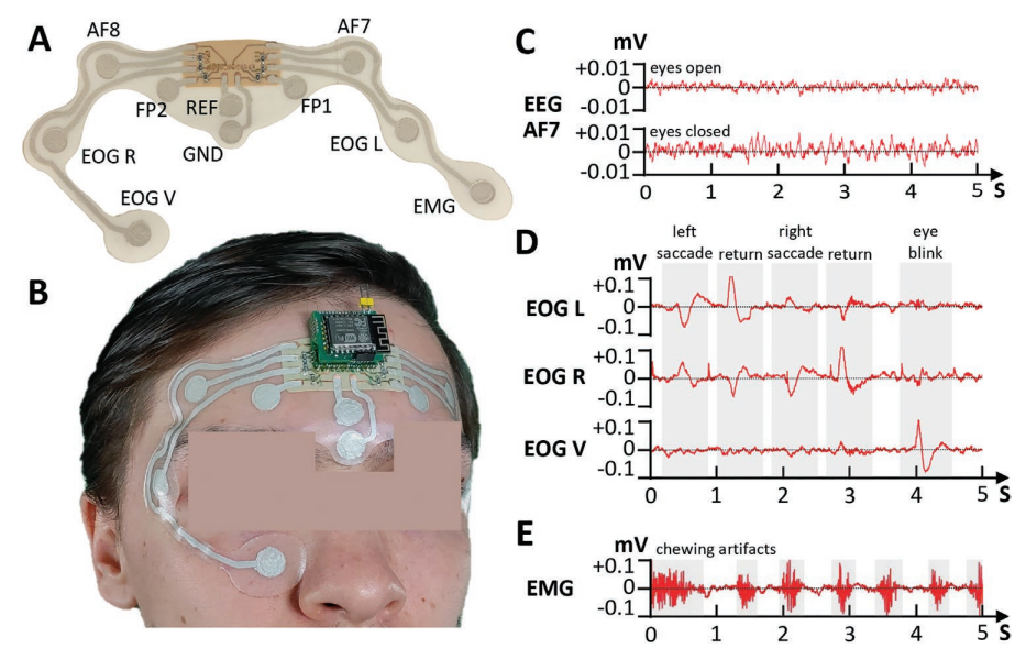
A) EEG/EOG/EMG patch and identification of the electrodes. B) Placement of the patch in the user’s face and forehead. C) Berger effect in EEG waves. When a user opens their eyes, the alpha rhythm is attenuated in amplitude. The higher amplitude of the acquired EEG signal when the user keeps their eyes closed can be observed in the plots. D) Eye movement detection through the EOG electrodes placed near the eyes. We can observe that the left and right electrodes show opposite polarities when lateral eye movement is detected. Eyeblinks, which are a predominantly vertical movement, are detected with higher amplitude by the EOG electrode placed below the user’s eye. E) Muscle artifacts from masticatory movement detected recorded by the EMG electrode placed on top of the masseter muscle.
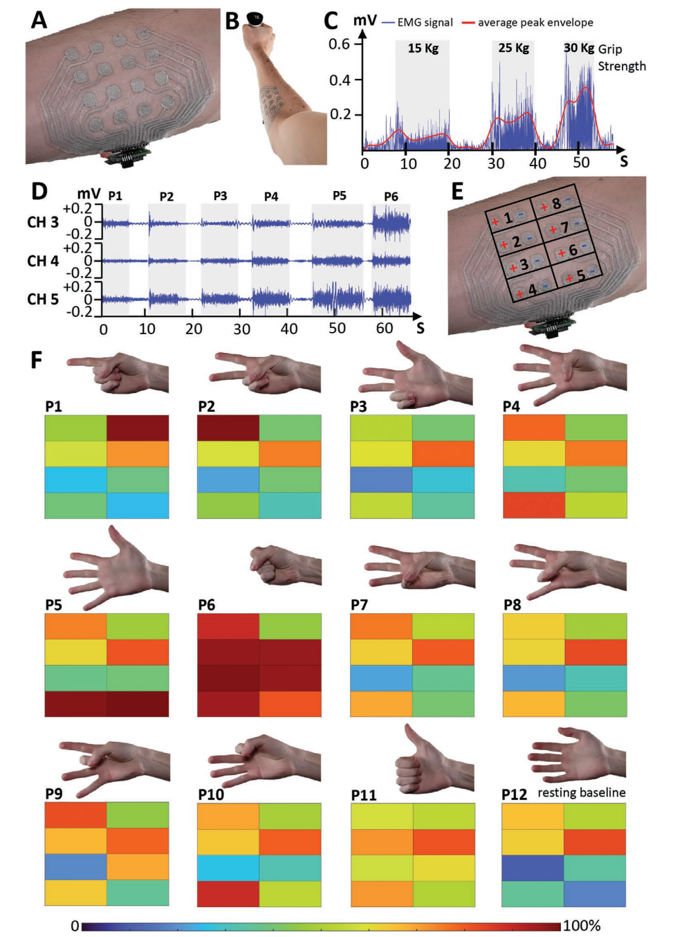
A) 16 electrode EMG patch. B) Setup for gripping force measurement with the EMG patch placed on the proximal portion of the anterior right forearm of the user, while grabbing a hand grip dynamometer. C) EMG signal (channel four) after full-wave rectification for different gripping forces and averaged peak envelope. D) EMG signals acquired from three channels for six distinct hand poses. E) Channel positions and polarity of the electrodes on the EMG patch placed on the right forearm. F) Scaled average amplitude of the eight EMG signals for 12 distinct hand poses.